
DIN Rail Mounted Industrial Patch Panel With 48 x LC Connectors

Industrial DIN Rail Fibre Patch Panel With top removed showing metal splice cassettes

Industrial DIN Rail mounted Fibre Patch Panel End View showing metal splice cassettes
Overview
The Case Communications Industrial DIN Rail Splice & Patch Panel is ideally suited to installations where space is at a premium. In addition to providing a fibre termination and patching point, the unit can also be used as a simple through Splicing enclosure or Spur unit, or a combination of these.
There are various mounting options available including DIN Rail, C-Rail and Panel mounting. This allows for the unit to be located and mounted virtually anywhere inside a rack, potentially saving space and reducing cable runs. Incoming plant cable/s can be routed in from the top or bottom (up to 4 entries).
Cables are secured within the integral adjustable clamps. A range of cable sizes can be secured from 6-22mm ø. Optional central strength member anchor points are also available. Access to the inside of the unit is quick and easy by undoing the 2 quarter-turn fasteners and removing the steel protection cover.
A laser warning sign located on the removable cover alerts users to the fact that hazardous laser radiation may be present at the unit or contained therein.
The industrial DIN rail fibre patch panels have in-built fibre management ensuring that the minimum bend radius is adhered to. Integral Splice cassettes with built-in 12-fibre management make splicing safe and convenient. Fibre expansion kits are available comprising of an additional 12-way splice cassette loaded with fibre pigtails, and replacement bulkhead panel pre-loaded with bulkhead connectors.
Cable Types
The material used on the jacket of the Fibre optic cable is specific to the application. The material determines and mechanical robustness, and the cables ability to withstand, oil resistance, ultra violet light from the sun (which can make the cable brittle), and also its suitability for use indoors ( for example not using Halogen). These days PVC is being replaced by Halogen free alternative materials, this is being driven by stricter regulations.
| Material | Halogen Free | UV Resistance | Notes |
| LSFH Polymer | Yes | Good | Good for indoor use |
| Polyvinyl chloride (PVC) | No | Good | Being replaced by LSFH Polymer |
| Polyethylene (PE) | Yes | Poor | Good for outdoor applications inside ducts, not to be exposed to sunlight |
| Polyurethane (PUR) | Yes | Good can withstand UV | Highly flexible cables generally not used in ducts. For example tacked to fencing or walls |
| Polybutylene terephthalate (PBT) | Yes | Fair | Good for indoor use |
| Polyamide (PA) | Yes | Good | Indoor and outdoor use, in ducts and buildings. More widely used. |
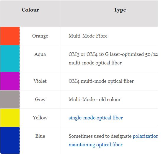
Cord Jacket Color
The buffer or jacket on patchcords is often color-coded to indicate the type of fiber used. The strain relief “boot” that protects the fiber from bending at a connector is color-coded to indicate the type of connection. Connectors with a plastic shell (such as SC connectors) typically use a color-coded shell. Standard color codings for jackets (or buffers) and boots (or connector shells) are shown below:
Technical Specifications
| Dimensions | Width: 250mm Depth: 150mm NB. Add 30mm for patch leads each side (15 x cable diameter) Height: 150mm |
| Materials | Top Cover: Mild Steel Main body: Aluminum |
| Finish | External: RAL 9001 (Cream) Fine textured Internal: Aluchrome |
| Mounting | DIN Rail, C-Rail and Panel, anyway up |
| Capacity | Up to 48-way |
| Cable access | 4 x entry points via side mounted adjustable cable clamps. NB. Card frame can be mounted either way up |
| Accessories | Strength member supports Expansion kits, pigtails Bulkhead adaptors Splice cassettes, diverse routing |
Typical Losses in a fibre link
There are a number of ways to determine the loss for a particular fibre optic link. The easiest and mostaccurate way is to perform an Optical Time Domain Reflectometer (OTDR) trace of the link. This will give you the actual loss values for all the components on that link (connectors, splices and fibre loss etc.) In the absence of an actual OTDR trace, there are two alternatives that can be used to estimate the power requirement of the link.
- Estimate the total linkloss across the fibre optic link if the fibre length variables are know.
- Estimate the maximum fibre distance if the optical budget and loss variance are known.
Loss variable are connectors, splices and attenuations per kilometer of the fibre. If the actual losses for all components are not known an estimate for each is needed to complete the calculations. In this case we would need to take a worst case approach to ensure there is adequet power available for the link. The following table includes commonly accepted loss values used in these calculations.
Fibre Type |
Wavelength |
Fibre attentuation per km |
Fibre attention per km (new fibre) |
Connector Loss |
Splice Loss |
| Multimode 50/125um | 850nm | 3.5dB | 2.5dB | 0.75dB | 0.1dB |
| 1300nm | 1.5db | 0.8dB | 0.75dB | 0.1dB | |
| Multimode 62.5 / 125um | 850nm | 3.5dB | 3.0dB | 0.75dB | 0.1dB |
| 1300nm | 1.5dB | 0.7dB | 0.75dB | 0.1dB | |
| Single Mode 9um | 1310nm | 0.4dB | 0.35dB | 0.75dB | 0.1dB |
| Single Mode 9um | 1550nm | 0.3dB | 0.22db | 0.75dB | 0.1dB |
IEEE Recommended maximum cable distances
Standard |
Data Rate |
Cable type |
IEEE Standard Distance |
| 10BASE-FL | 10 Mbps | 850nm Multimode 50/125um or 62.5/125um | 2km |
| 100BASE-FX | 100Mbps | 1300nm Multimode 50/125um or 62.5/125um | 2km |
| 100BASE-SX | 100Mbps | 850nm Multimode 50/125um or 62.5 /125um | 300m |
| 1000BASE-SX | 1000Mbps | 850nm Multimode 50/125um | 550m |
| 850nm Multimode 62.5/125um | 220m | ||
| 1000BASE-LX | 1000Mbps | 1300nm Multimode 50/125um or 62.5/125um | 550m |
| 1300nm Single Mode 9/125um | 5km | ||
| 1000BASE-LH | 1000Mbps | 1550nm Single Mode 9/125um | 70km |
Example Link Loss on 20km Link using 1550nm and 9um
- Splices over 20km at one every 6km = 4 Splices with 0.1dB loss per splice = 0.4db
- Fibre loss at 0.3db per km (old fibre) = 20km x 0.3= 6db
- Connector loss (1 Patch Lead per end with 2 connections Patch lead to Patch Panel to Patch Panel to CPE each end ) = 4 x 0.75db= 3dB (NB Patch panel and Patch leads should be kept clean to reduce loss)
- Total Loss for 20km 9.4db
Ordering Information
| PRODUCT | PART NUMBERS |
|---|---|
| LC-SPLICE AND PATCH PANELS | |
| 12 Way 6 LC Dual Adaptors Single Mode | SP-12-LC-SM-DIN |
| 24 Way 12 LC Dual Adaptors Single Mode | SP24-LC-SM-DIN |
| 36 Way 18 LC Dual Adaptors Single Mode | SP-36-LC-SM-DIN |
| 48 Way 24 LC Dual Adaptors Single Mode | SP-48-LC-SM-DIN |
| 96 Way 48 LC Dual Adaptors Single Mode | SP-96-LC-SM-DIN |
| ST-SPLICE AND PATCH PANELS | |
| 12 Way 6 ST 62.5 Dual Adaptors Multi-Mode | SP-12-ST-62.5-MM-DIN |
| 24 Way 12 ST 62.5 Dual Adaptors Multi-Mode | SP-24-ST-62.5-MM-DIN |
| 36 Way 18 ST 62.5 Dual Adaptors Multi-Mode | SP-36-ST-62.5-MM-DIN |
| 48 Way 24 ST 62.5 Dual Adaptors Multi-Mode | SP-48-ST-62.5-MM-DIN |
| ST BIDI DIN RAIL SPLICE AND PATCH | |
| 24 Way, 24 x STC full duplex on one fibre patch panel | SP-24-STB-SM-DIN |
| RACK MOUNTED PATCH PANELS | |
| 1U 19 inch Splice & Patch Panel 12 core, 6 dual LC SM inc pigtails and adapters | SP-12-LC-SM |
| 1U 19 inch Splice & Patch Panel 24 core, 12 dual LC SM inc pigtails and adapters | SP-24-LC-SM |
| 1U 19 inch Splice & Patch Panel 48 core, 24 dual LC SM inc pigtails and adapters | SP-48-LC-SM |
Additional Information
Patch Panel Splice Patch DIN Rail Data Sheet (4278 downloads )
For more information please contact Case Communications