Industrial SFP’s-Small Form Factor Pluggables
- (SFP) stands for Industrial SFP’s – Small Form Factor Pluggables – there are compact, hot-pluggable transceiver used for both telecommunication and data communications applications.
- Industrial SFP’s-Small Form Factor Pluggables, form factor and electrical interface are specified by a multi-source agreement (MSA) under the auspices of the S.F.P Committee.
Small Form Factor Pluggable interfaces network devices, for example switches, routers, media converters or similar device to a fibre optic or copper networking cable. - It is a popular industry format jointly developed and supported by many network component vendors.
- The SFP transceivers are designed to support SONET, Gigabit Ethernet, 10Gbps Ethernet, Fibre Channel, and other communications standards. The word ‘Industrial’ indicates extended temperature operation, typically from -400C to +850C.
- SFP’s are available with a variety of receiver and transmitter specifications. This allows users to select the relevant transceiver for each link to provide the required optical range over the available fiber type (e.g. multi-mode fibre or single-mode fibre).
- Transceivers are also designated by their transmission speed. SFP modules are generally available in several different categories.
1 Gbit/s multi-mode fibre, LC connector, with black or beige extraction lever
- SX – 850 nm, for a maximum of 0.5km at 1.25 Gbit/s (Gigabit Ethernet). Other multi-mode SFP applications support even higher rates at shorter distances.
1.25 Gbit/s multi-mode fibre, LC connector, extraction lever colours not standardised
- SX+/MX/LSX (name dependent on manufacturer) – 1310 nm, for a distance up to 2 km. Not compatible with SX or 100BASE-FX. Based on LX but engineered to work with a multi-mode fibre using a standard multi-mode patch cable rather than a mode-conditioning cable commonly used to adapt LX to multi-mode.
Industrial SFP’s-Small Form Factor Pluggables 1.25 to 2.5 Gbit/s with LC connector, with blue extraction lever
1000BASE-SX (770nm ~ 860nm)
- Standard – IEEE 802.3Z
- 1000BASE-SX is an optical fiber Gigabit Ethernet standard for operation over multi-mode fiber using a 770 to 860 nanometer, near infrared (NIR) light wavelength.
- The standard specifies a maximum length of 220 meters for 62.5 μm/160 MHz×km multi-mode fiber, 275 m for 62.5 μm/200 MHz×km, 500 m for 50 μm/400 MHz×km, and 550 m for 50 μm/500 MHz×km multi-mode fiber. Fiber optic cable manufacturers have extended the reach of 1000BASE-SX to at least 1km when used with more modern fiber optic grades such as OM3 and OM4.
- This standard is highly popular for intra-building links in large office buildings, co-location facilities and carrier-neutral Internet exchanges.
- Optical power specifications of SX interface: Minimum output power = −9.5 dBm. Minimum receive sensitivity = −17 dBm.
- Connectors – ST, SC,LC,
1000BASE-LSX (1310nm)
- Standard – Proprietary
- 1000BASE-LSX is a non-standard but industry accepted term to refer to Gigabit Ethernet transmission. It is very similar to 1000BASE-SX but achieves longer distances up to 2 km over a pair of multi-mode fibers due to higher quality optics than a SX, running on 1310 nm wavelength lasers. It is easily confused with 1000BASE-SX or 1000BASE-LX because the use of -LX, -LX10 and -SX is ambiguous between vendors. The range is achieved with use of Fabry Perot laser transmitter.
- Connectors – LC, SC
1000BASE-LX (1270nm ~ 1355nm)
- Standard – IEEE 802.3Z
- 1000BASE-LX is an optical fiber Gigabit Ethernet standard specified in IEEE 802.3 Clause 38 which uses a long wavelength laser (1,270–1,355 nm), and a maximum RMS spectral width of 4 nm.
- 1000BASE-LX is specified to work over a distance of up to 5 km over 10 μm single-mode fiber.
- 1000BASE-LX can also run over all common types of multi-mode fiber with a maximum segment length of 550 m. For link distances greater than 300 m, the use of a special launch conditioning patch cord may be required.[28] This launches the laser at a precise offset from the center of the fiber which causes it to spread across the diameter of the fiber core, reducing the effect known as differential mode delay which occurs when the laser couples onto only a small number of available modes in multi-mode fiber.
1000BASE-LX10 (1260nm ~ 1360nm)
- Standard IEEE 802.3ah
- 1000BASE-LX10 was standardised six years after the initial gigabit fiber versions as part of the Ethernet in the First Mile task group. It is practically identical to 1000BASE-LX, but achieves longer distances up to 10 km over a pair of single-mode fiber due to higher quality optics. Before it was standardized, 1000BASE-LX10 was essentially already in widespread use by many vendors as a proprietary extension called either 1000BASE-LX/LH or 1000BASE-LH.
- Connectors – LC
1000BASE-EX (1310nm)
- Standard – Proprietary
- 1000BASE-EX is a non-standard but industry accepted term to refer to Gigabit Ethernet transmission. It is very similar to 1000BASE-LX10 but achieves longer distances up to 40 km over a pair of single-mode fibers due to higher quality optics than a LX10, running on 1310 nm wavelength lasers. It is sometimes referred to as LH (Long Haul), and is easily confused with 1000BASE-LX10 or 1000BASE-ZX because the use of -LX(10), -LH, -EX, and -ZX is ambiguous between vendors. 1000BASE-ZX is a very similar non-standard longer-reach variant that uses 1550 nm wavelength optics.
- Connectors LC, SC
1000BASE-BX10 (TX = 1260nm ~ 1360nm) (Rx = 1480 ~ 1500nm)
- Standard – IEEE 802.3ah
- 1000BASE-BX10 is capable of up to 10 km over a single strand of single-mode fiber, with a different wavelength going in each direction. The terminals on each side of the fiber are not equal, as the one transmitting downstream (from the center of the network to the outside) uses the 1490 nm wavelength, and the one transmitting upstream uses the 1310 nm wavelength. This is accomplished using a passive splitter prism inside each transceiver.
- Other, non-standard higher-powered single-strand optics commonly known as “BiDi” (bi-directional) utilize wavelength pairs in the 1490/1550 nm range, and are capable of reaching distances of 20, 40 and 80 km, or greater depending on module cost, fiber path loss, splices, connectors and patch panels. Very long reach BiDi optics may use 1510/1590 nm wavelength pairs.
- Connectors – LC
1000BASE-ZX (1550nm)
- Standard- Proprietary
- 1000BASE-ZX is a non-standard but multi-vendor term to refer to Gigabit Ethernet transmission using 1,550 nm wavelength to achieve distances of at least 70 km (43 mi) over single-mode fiber. Some vendors specify distances up to 120 km (75 mi) over single-mode fiber, sometimes called 1000BASE-EZX. Ranges beyond 80 km are highly dependent upon the path loss of the fiber in use, specifically the attenuation figure in dB per km, the number and quality of connectors/patch panels and splices located between transceivers
- ConnectorsSC, LC
1000BASE‑CWDM (1270nm ~ 1610nm)
- Standard – ITU G.694.2
- 1000BASE-CWDM is a non-standard but industry accepted term to refer to Gigabit Ethernet transmission. It is very similar to 1000BASE-LX10 but achieves longer distances up 40–120 km, and up to 18 parallel channels over a pair of single-mode fibers due to higher quality optics than LX10 and use of CWDM, running on 1270-1610 nm wavelength lasers.
- Use of CWDM requires a Mux/Demux unit at both ends of the fiber link, a CWDM MUX/DEMUX with corresponding wavelengths, and SFP with corresponding wavelengths. is it also possible to DWDM in serie to increase number of channels.
- Most uses Wavelengths: 1270 nm, 1290 nm, 1310 nm, 1330 nm, 1350 nm, 1370 nm, 1390 nm, 1410 nm, 1430 nm, 1450 nm, 1470 nm, 1490 nm, 1510 nm, 1530 nm, 1550 nm, 1570 nm, 1590 nm and 1610 nm
- CWDM is cheaper to use than DWDM, about 1/5-1/3 of the cost. CWDM is about 5-10 times more expensive the if you have the fiber available, then traditional -LX/-LZ transceivers.
- Connectors – LC
1000BASE‑DWDM (1528nm ~ 1565nm)
- Standard – ITU G.694.1
- 1000BASE-DWDM is a non-standard but industry accepted term to refer to Gigabit Ethernet transmission. It is very similar to 1000BASE-LX10 but achieves longer distances up 40–120 km, and up to 64 to 160 parallel channels over a pair of single-mode fibers due to higher quality optics than LX10 and use of DWDM, running on 1528-1565 nm wavelength lasers.
- The most used channels are CH17-61 on Wavelength 1528.77-1563-86 nm.
- To use DWDM it is necessary to use a Mux/Demux unit on both ends of the fiber link, a DWDM MUX/DEMUX with corresponding wavelengths, and SFP with corresponding wavelengths.[23] is it also possible to use CWDM in series to increase the number of channels.
- Connector LC
1000BASE-RHx (650nm)
- Standard – IEEE 802.3bv
- IEEE 802.3bv-2017 defines standardizes Gigabit Ethernet over step-index plastic optical fiber (POF) using -R 64b/65b large block encoding with red light (600–700 nm). 1000BASE-RHA is intended for home and consumer use (just clamping the bare POF), 1000BASE-RHB for industrial, and 1000BASE-RHC for automotive applications.
- Connectors FOT (PMD / MDI)
Optical interoperability
There may be optical interoperability with respective 1000BASE-X Ethernet interfaces on the same link. It is also possible with certain types of optics to have a mismatch in wavelength.
What is IEEE 802.3z?
IEEE Std 802.3z, extends the operating speed of local area networks to 1 billion bits per second (1000 Mb/s (1 Gbps)) for interconnecting high-performance switches, routers, and servers in the backbone of local area networks. Maintaining backward compatibility with the over-100-million-node installed base of 10 Mb/s and 100 Mb/s. A Key requirement of the standard was to be backwards compatible and to interwork with 10Mbps and 100Mbps.
What is DMI?
| Parameter | Symbol | Min | Max | Unit | Notes |
|---|---|---|---|---|---|
| Temperature monitor absolute error | DMI_Temp | -3 | 3 | Centigrade | Over operating temperature |
| Supply voltage monitor absolute error | DMI_VCC | -0.15 | 0.15 | Volt | Full operating range |
| RX Power monitor absolute error | DMI_RX | -3 | 3 | dB | |
| Bias current monitor | DMI_bias | -10% | 10% | mA | |
| TX power monitor absolute error | DMI_TX | -3 | 3 | dB |
DMI Stands for Dynamic Management Interface. It is a method of monitoring the fibre optic interface attached to the SFP’s.
The Dynamic Management Interface monitors transmit and receive levels, temperature and voltages and other critical parameters. More Information.
Gigabit SFP Fibre driver Models
| Part Number | Gigabit Ethernet | Fibre | Wave | Range | Max Tx Pwr | Min Rx Pwr | Download PDF |
| 885M-0.5D | IEEE 802.3z | Multi-Mode | 885nm | 0.5km | -4dBm | -18dBm | SFP-885-0.5D (2855 downloads ) |
| 1310nm SFP's | |||||||
| 813M-02D | IEEE 802.3z | Multi-Mode | 1310nm | 2km | -1dbm | -19dbm | SFP-813M-002D (2833 downloads ) |
| 813S-010D | IEEE 802.3z | Single Mode | 1310nm | 10km | -3dbm | -20dbm |
SFP-813S-010D (2809 downloads )
|
| 813S-020D | IEEE 802.3z | Single Mode | 1310nm | 20km | -2dbm | -23dbm | SFP-813S-020D (2702 downloads ) |
| 1550nm SFP's | |||||||
| 815S-030D | IEEE 802.3z | Single Mode | 1550nm | 30km | 30km | -21dbm | SFP-815S-030D (2802 downloads ) |
| 815S-050D | IEEE 802.3z | Single Mode | 1550nm | 60km | +1dbm | -24dbm | SFP-815S-050D (2969 downloads ) |
| 815S-070D | IEEE 802.3z | Single Mode | 1550nm | 70km | +5dbm | -24dbm | SFP-815S-070D (2772 downloads ) |
| 815S-090D | IEEE 802.3z | Single Mode | 1550km | 90km | +5dbm | -27dbm | SFP-815S-090D (2652 downloads ) |
| 815S-110D | IEEE 802.3z | Single Mode | 1550nm | 110km | +5dbm | -30dbm | SFP-815S-110D (2802 downloads ) |
| 815S-120D | IEEE 802.3z | Single Mode | 1550nm | 120km | +5dbm | -32dbm | SFP-815S-120D (2588 downloads ) |
| 815S-140D | IEEE 802.3z | Single Mode | 1550nm | 140km | +5dbm | -34dbm | SFP-815S-140D (2742 downloads ) |
SFP Pin Orientation
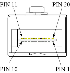
Industrial SFP’s Small Form Factor Pluggable Pins
SFP Pin Assignments
| Pin | Signal Name | Description |
| 1 | TGND | Transmit Ground |
| 2 | TX_Fault | Transmit Fault |
| 3 | TX_Disable | Transmit Disable |
| 4 | MOD_DEF(2) | SDA Serial Data Signal |
| 5 | MOD_DEF (1) | SCL Serial Clock Signal |
| 6 | MOD_DEF (0) | TTL Low |
| 7 | RATE SELECT | Open Circuit |
| 8 | RX_LOS | Receiver Loss of Signal, TTL High, open collector |
| 9 | RGND | Receiver Ground |
| 10 | RGND | Receiver Ground |
| 11 | RGND | Receiver Ground |
| 12 | RX- | Receive Data Bar, Differential PECL, ac coupled |
| 13 | RX+ | Receive Data, Differential PECL, ac coupled |
| 14 | RGND | Receiver Ground |
| 15 | VCCR | Receiver Power Supply |
| 16 | VCCT | Transmit Power Supply |
| 17 | TGND | Transmitter Ground |
| 18 | TX+ | Transmit Data, Differential PCEL ac coupled |
| 19 | TX- | Transmit Data Bar, Differential PCEL ac coupled |
| 20 | TGND | Transmitter Ground |
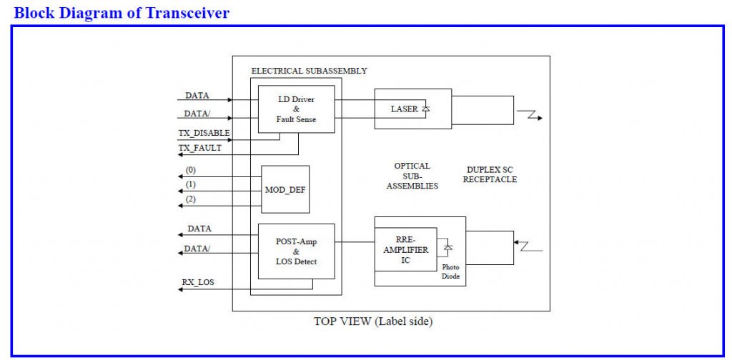
SFP Diagrams