Introduction to X-Ring Ethernet Industrial Ring Technology
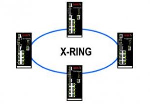
X-Ring Ethernet Industrial Ring Technology is supplied on the Case Communications range of Industrial Ethernet switches and provides an improvement over Spanning Tree and Rapid Spanning Tree. It provides a very rapid auto recovery if the network suffers a corrupt or broken link and prevent network loops. Case Communications X-Ring provides an Ethernet Ring between Industrial Ethernet switches, running at 10 Mbps, 100 Mbps or 1 Gbps. X-Ring can support up to 50 switches within a single Ring with a re-route time of 30 milli-seconds.The Rings geographic distance is only limited by the Fibre modules fitted to the switches so if using Single Mode SFPs capable of 120 km for example we could see a Ring of more than 6,000 km. When using copper then normal Ethernet rules apply.Multiple Rings can be connected using ‘Head-End’ Ethernet switches.
Configuration
X-Ring works by designating one switch in the Ring as the ‘Master’ switch and this switch controls the Ring. Should that switch fail another switch will take over as the ‘Master’ switch. There are two ways to configure a switch as the ‘Master’ switch. 1. Manual configuration –This is configured by using the built-in web interface.2. Auto selection by Mac address –When we designate more than 2 switches as ‘Master’ switches, then they will ‘auto select’ who is to become the ‘Master’ switch after a listening period, which starts on the switch’s boot up time. The switch that becomes the ‘Master’ switch is the switch with the smallest MAC address.If the listening period expires without receiving any SBPDU packets, then any switch with a MAC address smaller than the local switches MAC address, will become the master switch and start sending SBPDU packetsThe first diagram below shows the start-up sequence of an X-Ring Network, where all the units are set to ‘Master’. Each unit starts transmitting SBPDU packets after initialising The diagram to the right shows the switch with the smallest Mac address becoming the ‘Master’ and the other switches reverting to ‘Slaves’.
X-Ring Start-Up Sequence
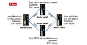
The diagram above shows the start-up sequence of an X-Ring network, where all the units are set to be a ‘Master’ switch. Notice each unit starts transmitting SBPDU packets after initialisation.
Auto-Selection of ‘Master’ Switch
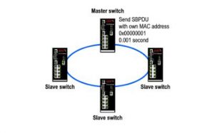
The switch with the smallest Mac address becoming the ‘Master’ and the other switches reverting to ‘Slaves’.
Loop Detection
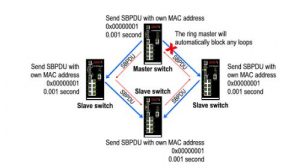
To avoid more than one loop being generated, the ‘Ring Master’ switch will automatically block its second ring port if it detects a loop.
X-Ring Automatic Recovery
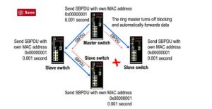
If any connection in X-Ring fails, the blocking switch will stop receiving the dual SBPDU packets, and will automatically stop blocking, turning the blocking port into a port forwarding port. Disconnect detection is within 10 ms.
For more information please contact Case Communications

